SCREEN LAYOUT
The Menu Bar

Menu bar
The Menu Bar runs across the top row of the screen and its main purpose (the selection of commands from the menus) is the same as with any other Windows application. In addition, the title bar area above the menu names is used to display certain prompt messages which indicate when the program has entered a particular editing or processing mode.
The Toolbars
Proteus also provides access to a number of its commands and modes through the use of toolbars. The toolbars can be dragged to any of the four edges of the application window. If you have a 4K monitor or have your machine set to use high DPI settings, the icons will upscale automatically. If they haven't, they can be forced from the System Settings command on the System Menu. You'll then need to close and open Proteus for the changes to take effect:

Setting the Icon size and the theme.
This is also where you might switch between light and dark themes or set the default fonts for text editor modules.
Command Toolbars
The tools located along the top of the screen (by default) provide alternative access to the menu commands, as follows:
| TITLE | TOOLBAR |
| File and Project Commands |  |
| Module Selection |  |
| View Toolbar |  |
| Edit Toolbar |  |
| Design Toolbar |  |
| Variant Selector |  |
| Board Selector |
|
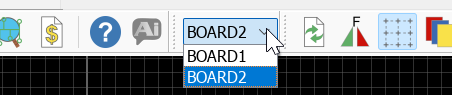
The first two toolbars belong to the Proteus application framework and appear in every module. The View, Edit and Design toolbars belong to the Schematic Capture module itself. The last two are drop-down controls rather than button bars: the variant selector chooses the active assembly variant, and the board selector chooses which board you are working on in a multi-board project.
If you are working on a relatively small monitor, you can hide any or all of the View, Edit and Design toolbars using the Toolbar Configuration command on the View menu. Only those three are listed there. The file and project commands, the module selection buttons, the mode selector, the orientation controls and the two selectors are always shown.
Mode Selector Toolbar
The toolbar located down the left hand edge of the screen select the editor mode, i.e. what happens when you click the mouse on the Editing Window.
| TITLE | TOOLBAR |
| Main Modes |  |
| Simulation Modes |  |
| 2D Graphics Modes |  |
The 2D Graphics group holds the line, box, circle, arc and path modes. The 2D Graphics Text, Symbols and Markers modes sit alongside that group rather than inside it, so they remain on the toolbar when the group is collapsed.
If some icons are not visible, then there will be a small black arrow on the first icon of that group:

If you right click on the icon it opens a menu with the rest of the icons:

If you want to permanently show the group, click on 'Expand the icon group'.
Note that the mode toolbar is always present and cannot be hidden. Every mode is also available from the Mode submenu at the foot of the Edit menu, which is useful if you would rather work from the keyboard.
Orientation Toolbar
The orientation toolbar displays and controls the rotation and reflection for objects placed onto the schematic.
| TITLE | TOOLBAR |
| Rotation |  |
| Mirror |  |
The rotation controls are Rotate Clockwise, Rotate Anti-Clockwise and Rotate 180 degrees; the mirror controls are X-Mirror and Y-Mirror. The edit box allows you to type a rotation angle in directly, but note that in the schematic module only orthogonal angles may be entered.
When an existing object is tagged, the Rotation and Mirror icons highlight in red to show that they will modify the orientation of an object on the layout. When the icons are not highlighted, they serve to determine the orientation for new objects.
The Editing Window
The Editing Window displays the part of the schematic that you are currently editing. The contents of the Editing Window may be redrawn using the Redraw Display command on the View menu, default key R. This also redraws the Overview Window. You can use this feature after any other command that has left the display somewhat untidy.
Panning
You can reposition the Editing Window over different parts of the design in several ways:
- By clicking left at a point on the Overview Window - this re-centres the Editing Window about the marked point.
- By clicking the middle mouse wheel on the editing window to 'pick up' the sheet and then moving the mouse to reposition the sheet. We refer to this feature as Track-Pan.
Note that you can roll the middle mouse wheel while in track-pan mode to zoom in and out of the schematic.
- By moving the mouse over the Editing Window, holding down the SHIFT key, and 'bumping' the pointer against one of its edges. This pans the display in the appropriate direction. We refer to this feature as Shift-Pan.
- By pointing in the Editing Window and pressing one of the Zoom keys (see below).This re-centres the display about the cursor position.
- By using the Center At Cursor command, default key F5, or its button on the View toolbar.
Zoom In / Zoom Out
You can magnify or reduce the display of the sheet using the Zoom In and Zoom Out commands that are also invoked by the F6 and F7 shortcut keys. Alternatively, you can roll the middle mouse wheel to zoom in or out of the area currently pointed to by the mouse. Pressing F8 invokes Zoom To View Entire Sheet, which displays the whole of the current sheet. You can also use the corresponding icons on the toolbar.
If the keyboard is used to invoke the command, then the Editing Window will be redrawn to display a region centred around where the mouse cursor was pointing before. This also provides a way to effect a pan by pressing the zoom key for the current level and simultaneously pointing with the mouse at where you want centre of the new display to be.
Variable Zoom
An arbitrary degree of magnification can be achieved using the Shift-Zoom feature. A given area of the sheet can be selected to fill the Editing Window by holding down the SHIFT key, pressing the left mouse button and dragging out a box around the desired area. The area can be marked on either the Editing Window or the Overview Window. You can also zoom to an area by clicking the Zoom Area icon on the toolbar.
The Overview Window
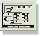
The Overview window
This window normally shows a simplified representation of the whole drawing, and has a half-inch grid on it. The cyan box marks the outline of the sheet border, whilst the green box indicates the area of the design currently visible in the Editing Window.
Clicking left at a point on the grid re-centres the Editing Window around this point, and redraws the Editing Window.
You can also use the Shift-Zoom and Track-Pan features detailed above on the Overview Window.
At other times, the Overview Window is used to display a preview of an object that is selected for placement. This Place Preview feature is activated in the following circumstances for any object which may be oriented:
- When an object is selected from the object selector.
- When the rotate or mirror icons are adjusted.
- When an object type icon is selected for an object whose orientation can be set (e.g. the Component Icon, Device Pin icon, etc.).
The place preview display is cleared automatically as soon as you proceed to place the object, or when you perform any operation other than those listed above.
The Overview Window pane can be dynamically hidden by right clicking on it and selecting the ‘Auto-Hide’ command from the resulting context menu. This is particularly useful once the parts you need are already on the schematic and you want to maximise the Editing Window space.
The Object Selector / Parts Bin
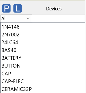
The Object Selector (Parts Bin)
The Object Selector is used for picking components, terminals, generators, graph types and so on from those that are available. It always carries a label indicating what it is listing and this serves as a prompt additional to the state of the Icon Panel as to which mode is current.
The width and position of the Object Selector can be adjusted in conjunction with the width and height of the Overview Window, as described above. You can also hide this pane to maximise the Editing Window space by right clicking on the Object Selector and selecting the Auto-Hide command from the resulting context menu.
The Context Menu for the Object Selector provides a number of mode specific options, giving you quick and easy access to functionality during schematic design.
Co-ordinate Display
The current co-ordinates of the mouse pointer are displayed down at the bottom right of the screen by default, and can be shown in imperial or metric units. The read-out, the grid and snap settings, the false origin and the Toggle X-Cursor command are all covered in full under Co-ordinate Display.